# Moderate Examples
# Moving Average and Median filters
The examples implement a moving averager and a median filter as explained fully in the application note Reducing noise and transients with custom real-time digital filtering (opens new window)
# Arithmetic Unit example
This arithmetic unit example can perform addition, subtraction, or multiplication of two input signals depending on a control register setting. A 2-bit control register to switch between different operations:
- 00 represents Input A + Input B;
- 01 represents Input A – Input B;
- 10 represents Input A * Input B;
- 11 will just pass Input A to Output A.
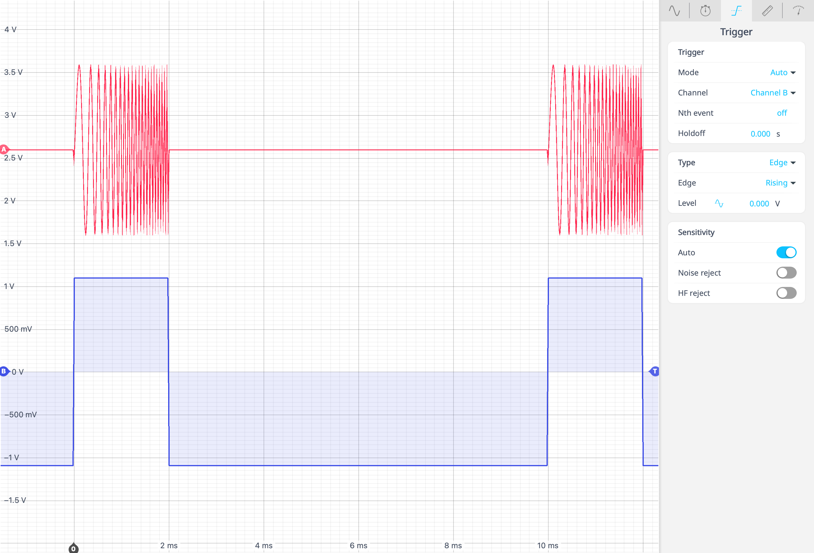
# Swept Frequency Pulse
A swept frequency pulse is often referred to as a chirped pulse, and is commonly used in radar applications. A chirped pulse is one where the transmitted frequency continuously changes (sweeps) throughout the duration of the pulse. However, with Moku Compile we can quite easily add this functionality into the Moku Waveform Generator. The following pulse is representative of the type of signal that would be used in a basic swept pulse system / RADAR.
# Input Divider
This is the implementation of OutputA = Control0 * (InputA / InputB).
Control register 0 "Control0" must be set to 1 so the Output A product is not 0. Control0 is a scalar of the Divider output, e.g. if Control0 = 2, the signal is scaled to 2x the original output. The output signal may have to be scaled significantly (Control0 > 100) to get a legible signal. For example in the screenshot below, Control0 was set to 6000 to get an output in the mV range.
The quotient signal can be routed to the Moku Oscilloscope in the contiguous Slot for quick viewing of the signal and to check the signal is as expected;