# Advanced
# Event Counter
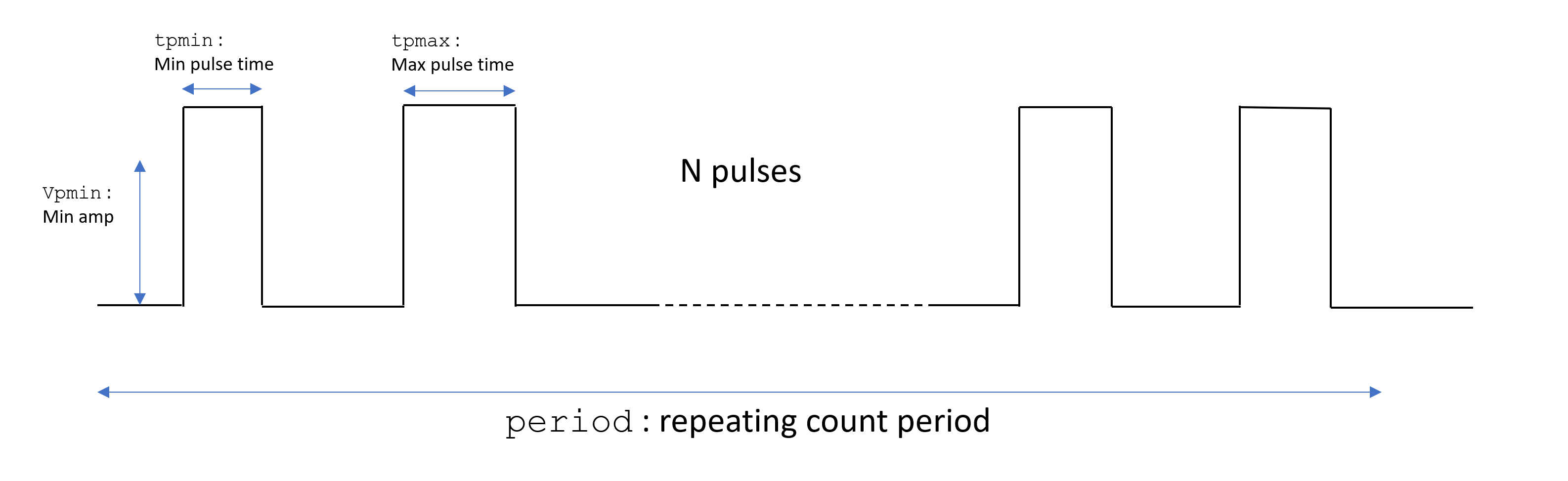
Counts the number of pulses of defined width in a period. If a count threshold is exceeded, an output flag is raised.
The parameters of the pulses (minimum and maximum width, minimum height) are configurable from Control Registers, as is the overall measurement period.
# Pinout and Registers
# Pinout
| Pin | Use |
|---|---|
| Input A | Pulse train input |
| Input B | Not used |
| Output A | Count threshold exceeded |
| Output B | Count threshold not exceeded (not OutputA) |
The values specific output when the count is and is not exceeded are defined as constants in the code.
# Registers
| Register | Bits 31-16 | Bits 15-0 |
|---|---|---|
| Control0 | t1 clock cycles | |
| Control1 | tpmax clock cycles | tpmin clock cycles |
| Control2 | mincount count | vpmin ADC Bits |
# VGA Waveform Display
This example implements a VGA driver, designed for Moku:Go. The two analog outputs are used for two color channels (not full RGB) while the digital pins are configured to provide the sync signals.
The waveform to be displayed is captured from Input A on a rising edge with a configurable directly-downsampled decimation factor, making this effectively a very simple Oscilloscope.
# Pinout and Registers
# Pinout
| Pin | Use |
|---|---|
| Input A | Waveform input |
| Input B | Not used |
| Output A | Red channel output |
| Output B | Blue channel output |
| Output C | H_Sync (bit 0), V_Sync (bit 1) |
Route Output C to the Digital I/O and ensure that Pins 1 and 2 are configured as outputs.
# Registers
| Register | Use |
|---|---|
| Control2 | Direct downsample decimation factor |
# Simple Boxcar Averager
# Overview
The boxcar averager instrument takes two inputs: a signal input and a gate (trigger) input. It starts integrating the input signal for a certain number of samples after receiving a trigger, then sends it to a secondary integrator to average a certain number of triggers events before sending it to the output.
This simple design is written directly in VHDL with hard-coded parameters. For a more featureful version that requires HDL Coder, see HDL Coder Boxcar or our example projects.
# Getting Started
# Signals and Settings
| Port | Use |
|---|---|
| Input A | Signal |
| Input B | Trigger |
| Output A | Average Out |
| Output B | Not Used |
# DLO Actuator Driver
This is a simple example of how to use the Moku:Go Digital I/O to drive an H-Bridge with PWM and decode position encoders.
It takes target positions as register values and drives the actuator to those positions at a configurable speed and with configurable overshoot to help mitigate mechanical hysteresis.
This is part of a collaboration between Liquid Instruments and Floquet.AI.
# DC Sequencer
A customer required a system that output a series of DC values, stepping between them based on a trigger input. Some AWG units can segment their memory and transition between segments in this way, but it is a complicated process given each segment contains a single value.
Using Moku Compile, a simple sequencer was written with custom Schmitt trigger logic and a pre-defined list of DAC output values. The debounced trigger was output from the logic as well, to be used downstream.
The Schmitt trigger levels are configurable through a Control register, the DC value sequence is hard-coded.