# Output Interpolation
Moku Compile allows users to implement custom logic on their Moku device by processing data at the FPGA clock rate. Output interpolation is an optional feature that enables the output signals to reach the higher sampling rates of the system. This is achieved by interpolating intermediate samples between consecutive data points, effectively increasing the output sample rate. When output interpolation is disabled, the output holds the current sample value until the next processed sample becomes available, resulting in a step-wise (zero-order hold) behavior.
Interlacing support
Output interpolation is not available when using interlaced designs. In interlaced designs, the output samples are dictated directly by the custom logic operating at the higher effective sampling rate. Output interpolation is therefore primarily applicable to CustomInstrument and CustomWrapper architectures, which operate at the base FPGA clock rate.
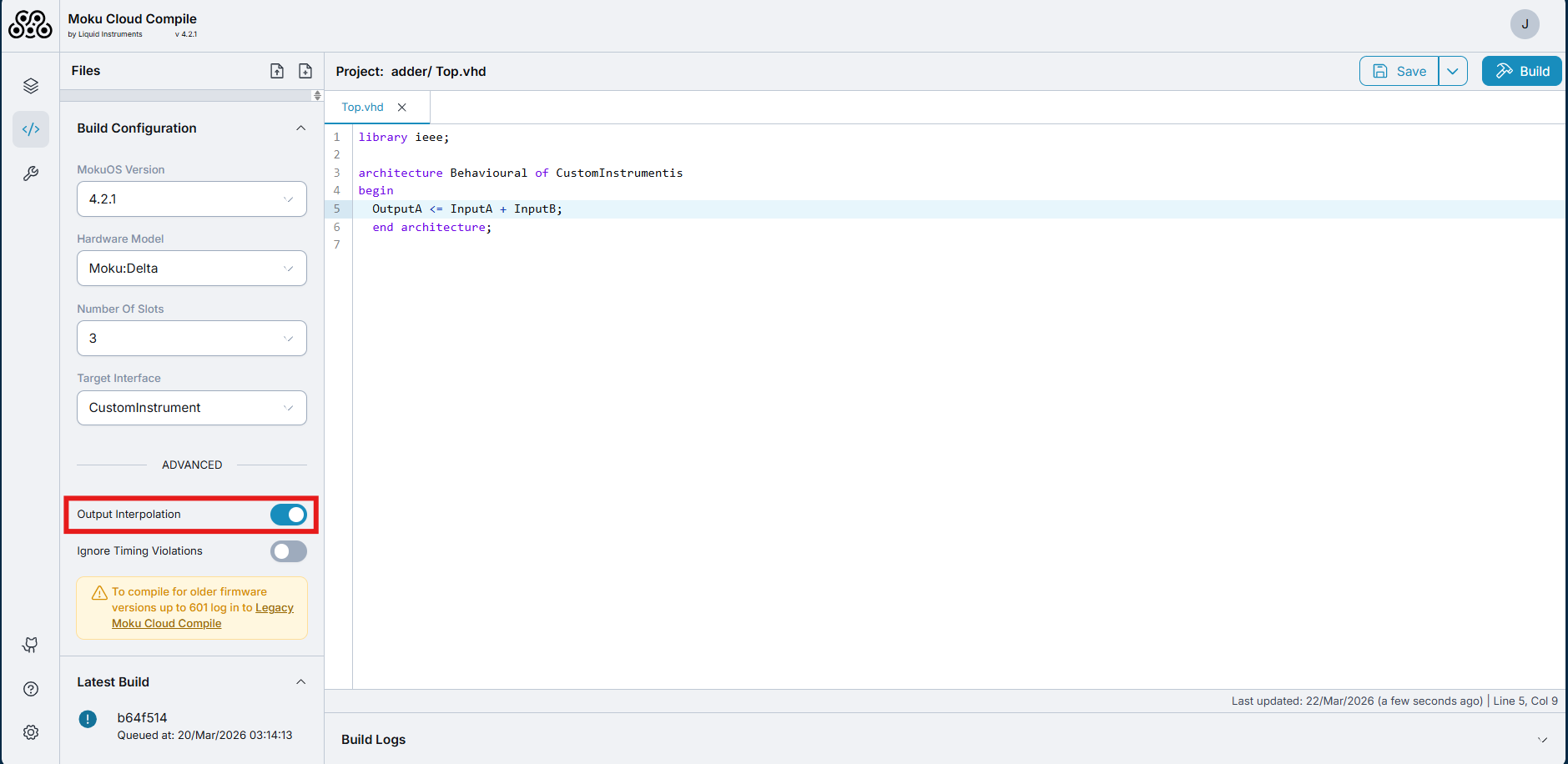
When using Moku Cloud Compile: The Output interpolation option can be toggled under Advanced setting under Build Configuration as shown below:
When using On-premises Moku Compile : The Output interpolation can be
given as the argument --interpolation when executing the run command as below:
mokucli mc run --src-dir \path\to\source\directory --hw-version <moku-device> --slots <number-of-slots> --interface <wrapper-name> --interpolation <True/False>
# Output interpolation rates
Moku:Delta
| 3 slots | 5 slots | 8 slots | |
|---|---|---|---|
| Core clock | 312.5 MHz | ||
| Maximum sampling rate | 5 GSa/s | 1.25 GSa/s | 625 MSa/s |
Moku:Pro
| 4 slots | |
|---|---|
| Core clock | 312.5 MHz |
| Maximum sampling rate | 1.25 GSa/s |
Moku:Lab
| 2 slots | 3 slots | |
|---|---|---|
| Core clock | 125 MHz | |
| Maximum sampling rate | 500 MSa/s | 250 MSa/s |
Moku:Go
| 2 slots | 3 slots | |
|---|---|---|
| Core clock | 31.25 MHz | |
| Maximum sampling rate | 125 MSa/s | 62.5 MSa/s |
# Example of output interpolation
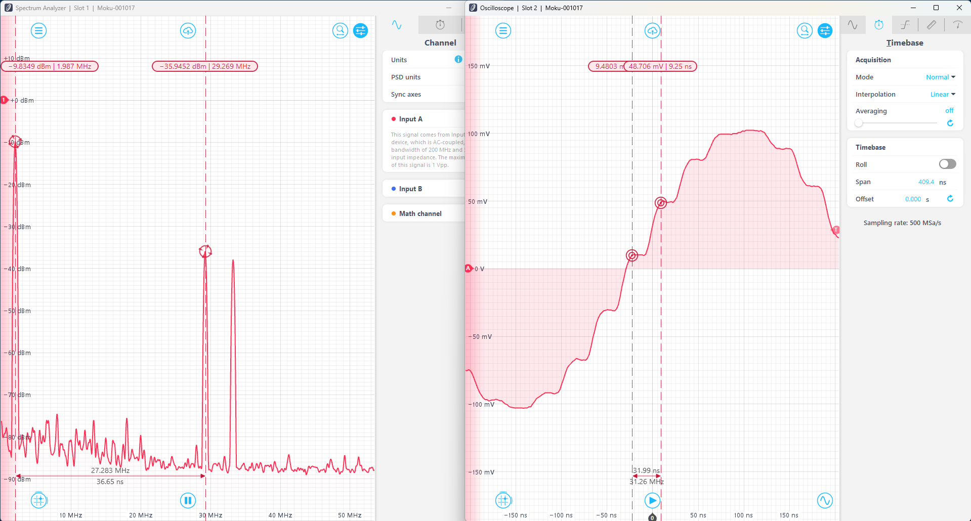
The difference in the data processing can be shown by comparing the adder example with and without the output interpolation. The adder code computes the sum and difference of the two inputs, A and B, routing the sum and difference signals to outputs A and B respectively. In this example, the adder code is synthesized for Moku:Go. This is uploaded to Slot 2 of a 2-slot Multi-Instrument Mode configuration, with a Waveform Generator deployed in Slot 1, generating a 2 MHz sine wave into InputA of the Custom Instrument. InputB of the Custom Instrument is not connected to any source and thus the code acts as a relay logic. The output of the adder is routed to Output A and B of the Moku:Go, which is connected to an external Moku:Lab (operating at 500MSa/s) where the signal is simultaneously observed on an external Oscilloscope and a Spectrum Analyzer.
With no interpolation, samples are held at the last known value for 32 ns (the clock rate of the Moku:Go) before outputting the next sample. This results in a stair-like waveform that looks severely quantized. The spectrum analyzer shows a peak value at 2 MHz, with components at 29.25 MHz and 33.25 MHz. The additional components are an effect of aliasing on the output signal, and correspond to different Nyquist zones.
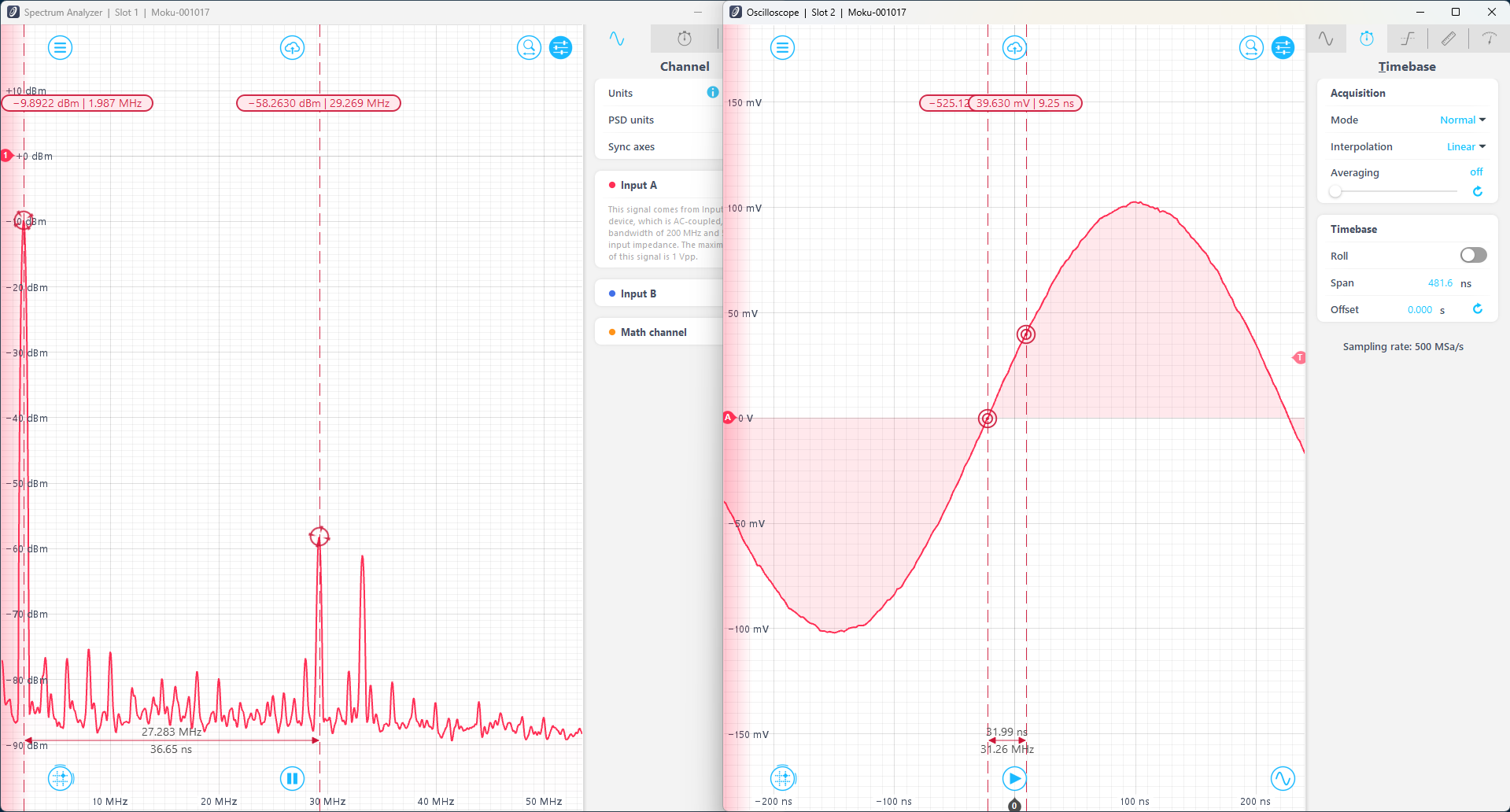
With output interpolation, the samples are filled in based on linear interpolation. This creates a smoother waveform and a fairer representation of the sinusoid signal. The higher frequency components are still visible in the frequency domain, but have a reduced amplitude.
Effective sampling rate
Note that output interpolation acts on known samples, and does not create an effective higher sampling rate. Signals after output interpolation are still subject to the Nyquist rate limited by the FPGA clock rate. This can be observed in the Spectrum Analyzer in the above pictures, where the sine wave has components at 29.25 MHz and 33.25 MHz. To access higher rates, please refer to interlacing.