# Interlacing
Interlacing is a technique to access the full sampling rate capability of Moku device in Multi-Instrument Mode. Moku devices use the FPGA system clock to process data. By default, the Custom Instrument uses one data sample per clock cycle and thus operate at a sampling rate dictated by the FPGA clock.
This sampling rate can be increased by interlacing - processing multiple samples at the same FPGA clock rate simultaneously. For example, accessing 4 samples at 31.25 MHz clock on the Moku:Go increases the effective sample rate to 125 MSa/s. This parallel processing of samples is referred to as interlacing and can be done using both Moku Cloud Compile and On-premises Moku Compile.
Subscription requirements
You need to subscribe to the Enterprise or Premium tier of Moku Compile to access the interlacing feature. Base tier users are restricted to sampling at the clock rate.
The interpolation factor defines the CustomInstrumentInterlaced entity. This is defined as per wrappers, where the interlacing factor is set by the number of samples. Depending on the hardware model and the number of slots used in Multi-Instrument Mode, the input and output interlacing factor varies.
Moku:Delta
| 3 slots* | 5 slots* | 8 slots* | |
|---|---|---|---|
| Core clock | 312.5 MHz | ||
| Interlacing factor | 16 | 4 | 2 |
| Maximum sampling rate | 5 GSa/s | 1.25 GSa/s | 625 MSa/s |
Moku:Pro
| 4 slots* | |
|---|---|
| Core clock | 312.5 MHz |
| Interlacing factor | 4 |
| Maximum sampling rate | 1.25 GSa/s |
Moku:Lab
| 2 slots | 3 slots | |
|---|---|---|
| Core clock | 125 MHz | |
| Interlacing factor | 4 | 2 |
| Maximum sampling rate | 500 MSa/s | 250 MSa/s |
Moku:Go
| 2 slots | 3 slots | |
|---|---|---|
| Core clock | 31.25 MHz | |
| Interlacing factor | 4 | 2 |
| Maximum sampling rate | 125 MSa/s | 62.5 MSa/s |
# Interlacing vs Output Interpolation
Interlacing is different from Output Interpolation available on all devices. While both provides output samples at the higher sampling rates, the processing of the data points are different.
Output interpolation computes additional samples based on linear interpolation on the data points at the base rate. This means while the data is being generated at the higher sampling rate, the effective operating bandwidth is limited to the clock of the device.
On the other hand, interlacing would allow each data point to be individually computed based on the custom design itself.
The difference in the data processing can be shown by comparing the adder example with and without the interlacing effect. The adder code computes the sum and difference of the two inputs, A and B, routing the sum and difference signals to outputs A and B respectively. In this example, the adder code is synthesized for Moku:Go. This is uploaded to Slot 2 of a 2-slot Multi-Instrument Mode configuration, with a Waveform Generator deployed in Slot 1, generating a 10 MHz sine wave into InputA of the Custom Instrument. InputB of the Custom Instrument is not connected to any source and thus the code acts as a relay logic. The output of the adder is routed to Output A and B of the Moku:Go, which is connected to an external Moku:Lab (operating at 500MSa/s) where the signal is simultaneously observed on an external Oscilloscope and a Spectrum Analyzer. For illustration, InputA is a sine wave at 10 MHz, while InputB is null signal, effectively acting as a relay logic.
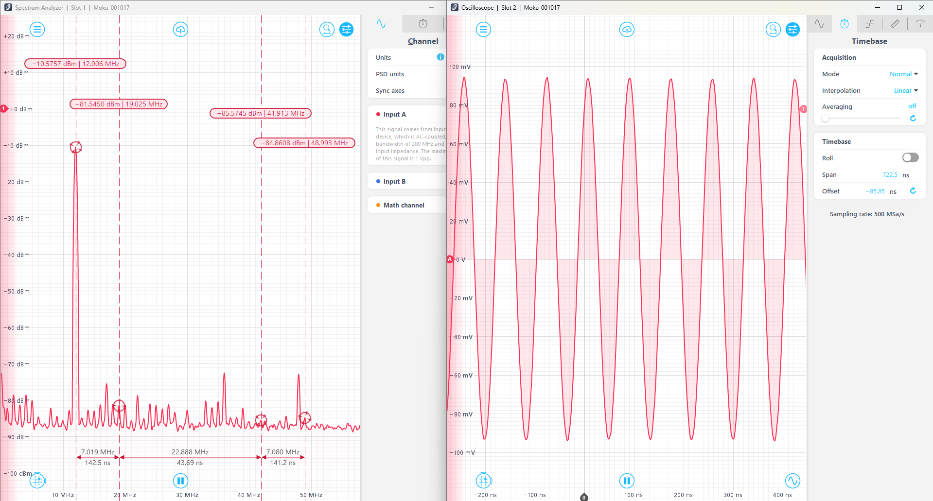
With no interlacing or interpolation, the inputs and outputs are sampled at the base clock rate of Moku:Go at 31.25 MHz or 32 ns. The signal updates after every 4 samples, giving it a step like structure. The same conclusion can also be shown using Spectrum Analyzer in frequency domain. For higher frequency signals, the spectrum wraps around 15.625 MHz when no interlacing is used.
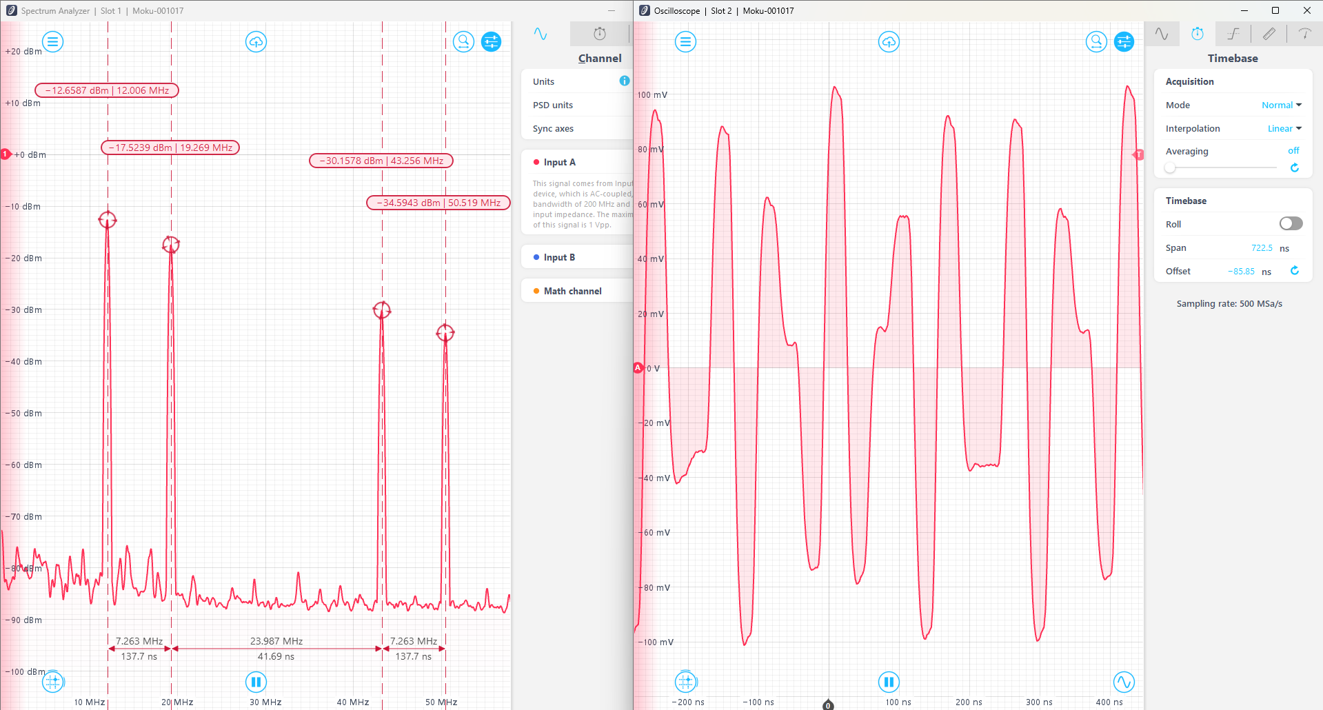
With output interpolation, the outputs have a smoother appearance and better showcases a sinusoid waveform. However, the sampling bandwidth is still restricted to 31.25 MHz, with the signal spectrum restricted to 15.625 MHz.
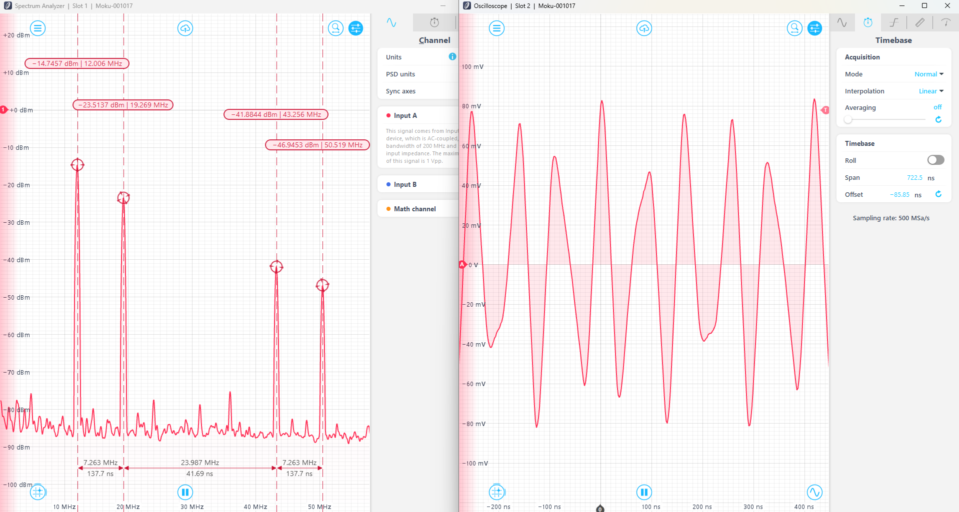
With interlacing, the inputs and outputs are sampled at 125 MSa/s, and thus the signal updates at the rate of 8 ns (1/125 MHz). With interlacing, the spectrum can access the full rate and can access up to 62.5 MHz spectrum.